GitHub#
Abstract#
Components#
- LTC6990 VCO
- AC power supply (for carrier and message signals)
- DC power supply
- Capacitor
- Resistors
- Diode (IN5818)
- OPAMP (AD549)
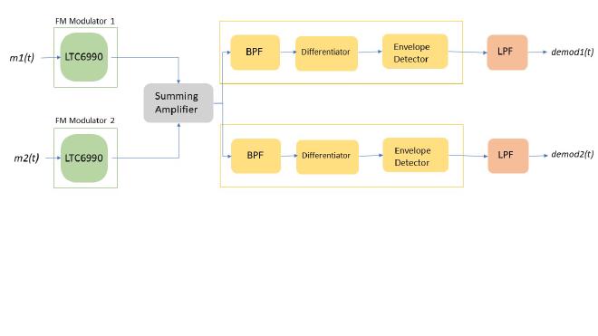
Circuit Block Diagram#
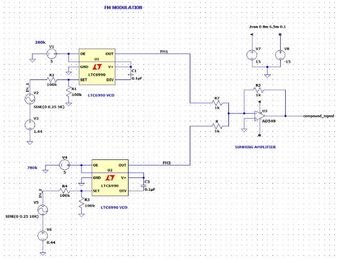
Circuit#
FDM Transmitter#
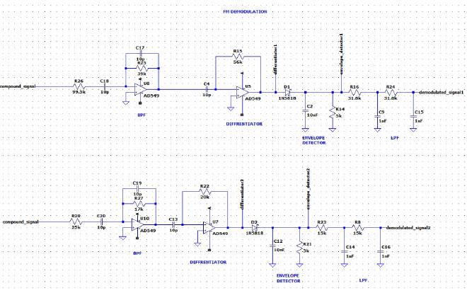
FDM Receiver#
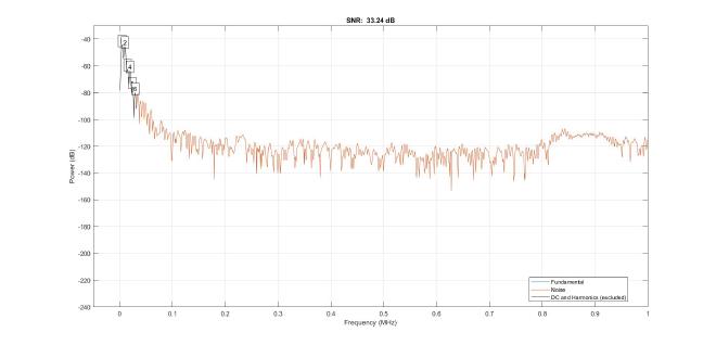
Signal To Noise Ratio#
With Guard Bands#
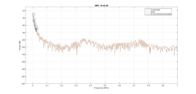
Output 1
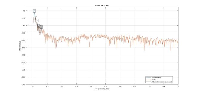
Output 2
Without Guard Bands#
Output 1
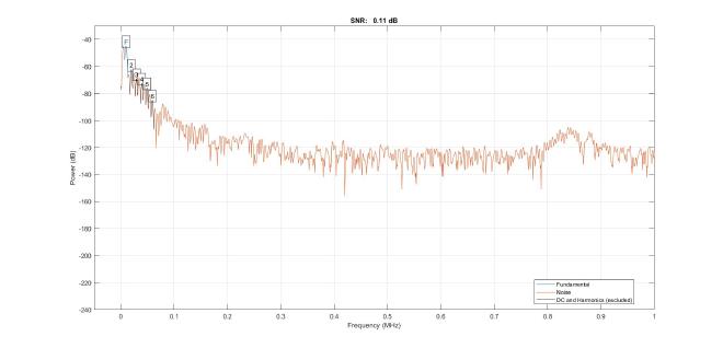
Output 2
---Therory#
Frequency Modulation:#
Frequency Modulation is the process of varying the frequency of the carrier signal linearly with the message signal. Hence, in frequency modulation, the amplitude and the phase of the carrier signal remains constant. The frequency modulation method of transmitting signals, especially in radio broadcasting, in which the value of the signal is given by the frequency of a high-frequency carrier wave. In FM radio transmission, for example, the signal to be carried is a sound wave, and its increasing and decreasing value is reflected in the increasing and decreasing frequency of a radio frequency carrier wave.
The carrier frequency will be minimum (fc min) when the input signal is at its lowest. The carrier deviates from its normal value. The frequency of the carrier will be at its normal value (free-running) fc when the input signal value is 0V. There is no deviation in the carrier. The figure shows the frequency of the FM wave when the input is at its max, 0V, and at its min.
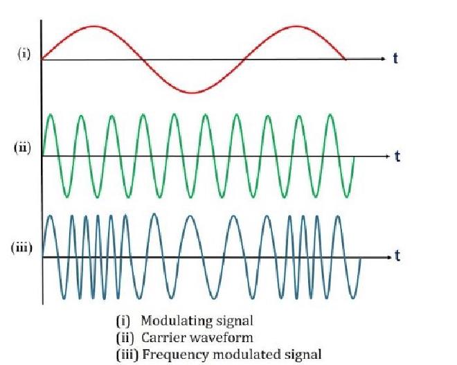
Frequency Modulation
Mathematical Expression:#
\(y(t) = A_c cos(2 \pi f_ct + \frac{f_\Delta}{f_m}sin(2 \pi f_mt))\)
Were \(f_c\) is the carrier frequency
\(f_m\) is message signal frequency
\(f_\Delta\) is the frequency deviation
\(\frac{f_\Delta}{f_m}\) is the modulation index.
Modulation Index#
The modulation index of an FM wave is defined as under :
\(h = \frac{\Delta f}{f_m} = \frac{f \Delta |x_m(t)|}{f_m}\)
The modulation index is very important in FM because it decides the bandwidth of the FM wave. The modulation index also decides the number of sidebands having significant amplitudes.
In AM, the maximum value of the modulation index m is 1 . But, for FM, the modulation index can be greater than 1.
Bandwidth#
Bandwidth is one of the main elements of FM signal. In FM signal, the sidebands will extend either side which will extend to infinity; however, the strength of them drops away. Auspiciously, it is the potential to restrict the BW of an FM signal without changing its value excessively.
Recall, the bandwidth of a complex signal like FM is the difference between its highest and lowest frequency components and is expressed in Hertz (Hz). Bandwidth deals with only frequencies. AM has only two sidebands (USB and LSB), and the bandwidth was found to be \(2f_m\).
In FM it is not so simple. FM signal spectrum is quite complex and will have an infinite number of sidebands as shown in the figure. This figure gives an idea, how the spectrum expands as the modulation index increases. Sidebands are separated from the carrier by \(f_c ± f_m \), \(f_c ± 2f_m\) ,\(f_c ± 3f_m\), and so on.
If \(h « 1\) the modulation is called narrowband FM (NFM), and its bandwidth is approximately\($B = 2f_m\)
For wideband FM we use Carson’s rule which states that nearly all (≈98 percent) of the power of a frequency-modulated signal lies within a bandwidth B of:
\(B = 2(\Delta f +f_m)\)
\(B = 2(\beta +1)f_m\)
Voltage Controlled Oscillator (VCO):#
The voltage-controlled oscillator (VCO) is a device whose frequency changes linearly with an input voltage. It is used to perform direct frequency modulation on signals. VCO has a center frequency fc and the input control) voltage m(t) modulates the instantaneous frequency around this center frequency.
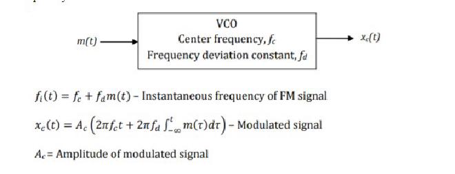
FM generation using VCO
The mean frequency of these oscillators is determined by an RC circuit. The controllable part of the VCO is its frequency, which may be varied about a mean by an external control voltage. The variation of frequency is close to linear, with respect to the control voltage, over a large percentage range of the mean frequency
LTC6990 Oscillator#
The LTC6990 is a precision silicon oscillator with a programmable frequency range of 488Hz to 2MHz. It can be used as a fixed-frequency or voltage-controlled oscillator (VCO)
The output signal frequency expressed as:
\(F_{OUT} = 1MHz - 0.5V_{CTRL}MHz/V\)
Frequency Demodulation#
FM demodulation is a key process in the reception of a frequency modulated signal. Once the signal has been received, filtered, and amplified, it is necessary to recover the original modulation from the carrier. It is this process that is called demodulation or detection.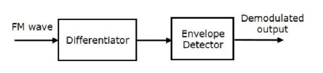
FM demodulation
Op-Amp based differentiator:#
An op-amp differentiator is an inverting amplifier configuration that produces output voltage amplitude which is proportional to the rate of change of the input voltage with respect to time. This means that the faster change in the input voltage signal, the greater the output voltage
change in response. It uses a capacitor in series with the input voltage. Normally, differentiating circuits are usually designed to respond to triangular and rectangular input waveforms.
It is used to convert the FM wave into a combination of AM wave and FM wave. This means it converts the frequency variations of FM waves into the corresponding voltage(amplitude) variations of AM waves. In this case, the output of the differentiator will be an AM modulated signal. The AM modulated signal can be then demodulated using an envelope detector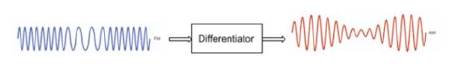
The Differentiator
The Envelope detector:#
An envelope detector is an electronic circuit that takes a (relatively) high-frequency amplitude modulated signal as input and provides an output, which is the demodulated envelope of the original signal.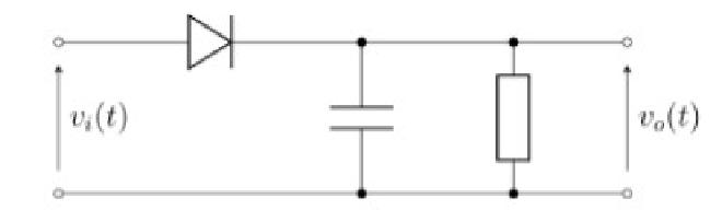
Envelope Detector
The capacitor in the circuit above stores charge on the rising edge and
releases it slowly through the resistor when the input signal amplitude falls. The diode in series rectifies the incoming signal, allowing current flow only when the positive input terminal is at a higher potential than the negative input terminal.
In the above equation, the amplitude term resembles the envelope of the AM wave and the angle term resembles the angle of the FM wave. Here, our requirement is the modulating signal m(t). Hence, we can recover it from the envelope of the AM wave using an envelope detector.
Finally, it is passed through a low pass filter to remove high-frequency components
Multiplexing#
Multiplexing is the process of combining multiple signals into one signal, over a shared medium. So basically it is a technique that allows the simultaneous transmission of multiple signals through a single channel. This, therefore, ensures the efficient utilization of channel bandwidth and channel resources
The device that does multiplexing can be called a Multiplexer or MUX.
There are mainly two types of multiplexers, namely analog and digital.
They are further divided into Frequency Division Multiplexing (FDM), Wavelength Division Multiplexing (WDM), and Time Division Multiplexing (TDM)
Frequency division multiplexing#
Frequency division multiplexing (FDM) is a technique of multiplexing that means combining more than one signal over a shared medium. In FDM, signals of different frequencies are combined for concurrent transmission
Concept and process#
In FDM, the total bandwidth is divided into a set of frequency bands that do not overlap. Each of these bands is a carrier of a different signal that is generated and modulated by one of the sending devices. Each signal to be transmitted modulates a different carrier. The frequency bands are separated from one another by strips of unused frequencies called the guard bands, to prevent overlapping of signals
The spectrum of composite FDM signals has been shown.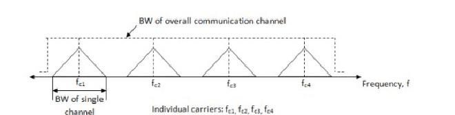
FDM
Different signals are thus added together in the time domain but they have a separate identity in the frequency domain.
The modulated signals are combined together using a multiplexer (MUX) in the sending end. The combined signal is transmitted over the communication channel, thus allowing multiple independent data streams to be transmitted simultaneously.
At the receiving end, the individual signals are extracted from the combined signal by the process of demultiplexing (DEMUX). The composite signal is applied to a group of bandpass filters (BPF). Each BPF has a center frequency corresponding to one of the carriers. The BPFs have an adequate bandwidth to pass all the channel information without any distortion. Each filter will pass only its channel and reject all the other channels. The channel demodulator then removes the carrier and recovers the original signal back.\
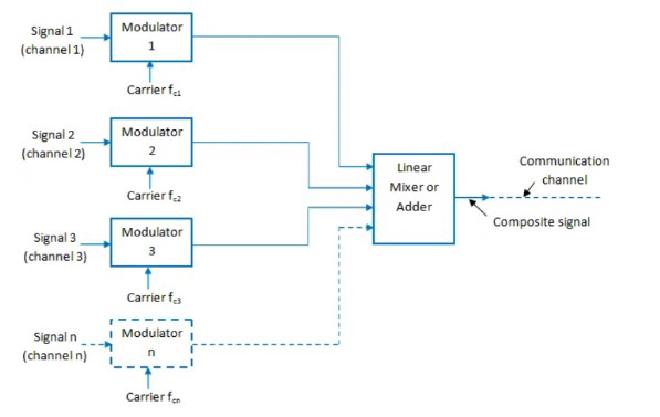
FDM Multiplexing process
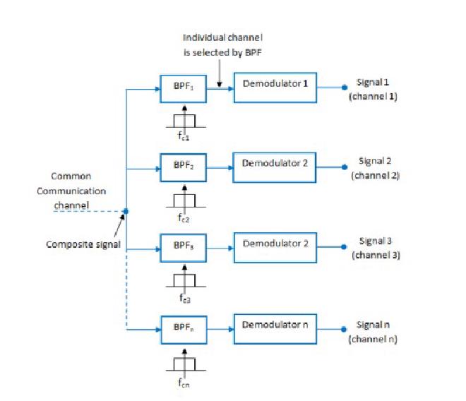
FDM Demultiplexing process
Linear Adder#
The summing Amplifier is one variation of inverting amplifiers. In an inverting amplifier there is only one voltage signal applied to the inverting input. This simple inverting amplifier can easily be modified to a summing amplifier if we connect several input terminals in parallel to the existing input terminals.
Bandpass Filter#
Band Pass Filter is a frequency selective filter circuit used in electronic systems to separate a signal at one particular frequency, or a range of signals that lie within a certain “band” of frequencies from signals at all other frequencies. The cut-off or corner frequency of the low pass filter (LPF) is higher than the cut-off frequency of the high pass filter (HPF) and the difference between the frequencies at the -3dB point will determine the “bandwidth” of the bandpass filter while attenuating any signals outside of these points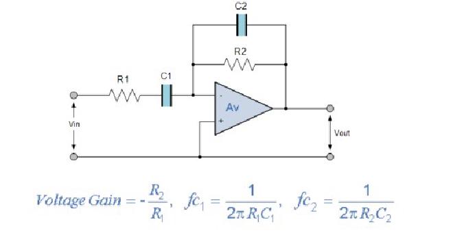
Bandpass Filter
Guard Band#
A guard band is a narrow frequency range that separates two ranges of wider frequency. This ensures that simultaneously used communication channels do not experience interference, which would result in decreased quality for both transmissions
Guard bands are used in frequency division multiplexing (FDM). In FDM, a number of signals are sent simultaneously on the same network, allocating separate frequency bands or channels to each signal. Guard bands are used to avoid interference between two successive channels.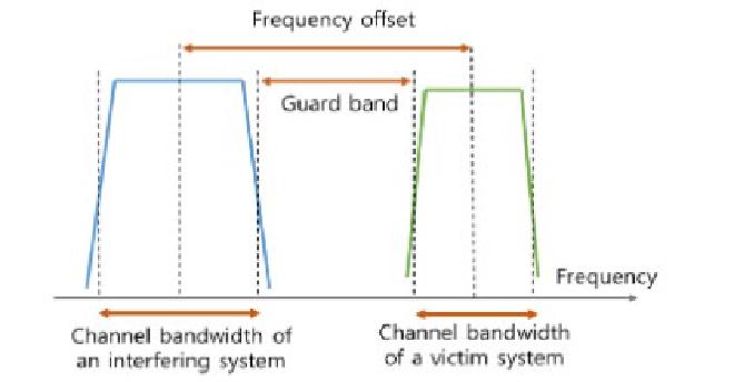
Guard Band
Advantages of FDM:#
- It does not need synchronization between its transmitter and receiver
- Frequency division multiplexing (FDM) is simpler and easy to demodulate.
- It is used for analog signals.
- A large number of signals (channels) can be transmitted simultaneously.
Disadvantages of FDM#
- It suffers from the problem of crosstalk.
- Intermodulation distortion takes place.
- Large bandwidth is required