GitHub#
Create a means for solar panels to track the sun :)
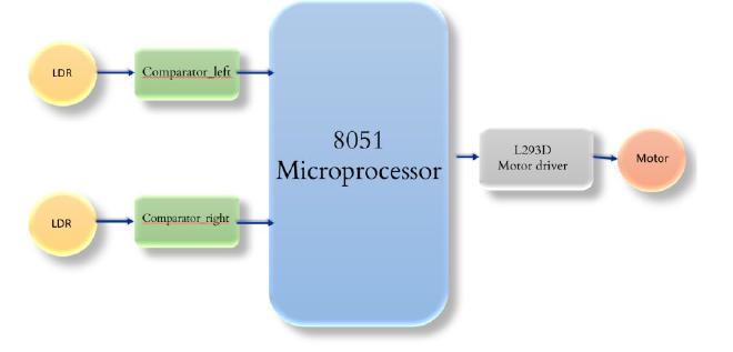
Block Diagram:#
Components:#
- AT89C51- 8051 Microcontroller
- 2 LDRs
- 2 LM324- Comparators
- 2 Buffers
- DC motor
- L293D- Motor driver
- 10 Resistors
- 2 Capacitors
- Crystal Oscillator- Clock
- Push-button
- 2 LEDs
LDR#
A LDR is a passive component that decreases resistance with respect to receiving luminosity (light) on the component’s sensitive surface. The resistance of a photoresistor decreases with an increase in incident light intensity[it exhibits photoconductivity]
LM324#
The operational amplifier LM324 IC can work as a standard comparator, and it comprises four independent op-amps internally. This IC is designed with low power, bandwidth, and high stability for operating with a single power supply over extensive voltage ranges.
L293D#
The L293D is a popular 16-Pin Motor Driver IC. A single L293D IC is capable of running two DC motors simultaneously; also, the direction of these two motors can be controlled independently. L293D consists of two H-bridge. For L293D Motor Driver, the motor supply is variable between 4.5 to 36V, and it provides a maximum current of 600mA. [we have given 5V Supply]
DC Motor#
A DC motor is a rotatory instrument that works on DC power to convert electrical energy into mechanical energy. DC motors can vary in size and power. It consists of two terminals, and some modules available in the market do not indicate the polarity. However, reversing the connections of these terminals will change the direction of rotation of the motor.
AT89C51#
The AT89C51 is an age-old 8-bit microcontroller from the Atmel family. It works with the popular 8051 architecture. It is a 40 pin IC package with 4Kb flash memory. It has four ports and altogether provides 32 Programmable GPIO pins
Software Used:#
➔ Proteus
➔ Keil μVision5
Algorithm:#
- Set P1 as input and P2 as output
- Monitor P1.0 and P1.1 and give output to L293D via P2 as follows:
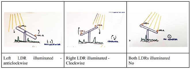
2.1. If P1.0 = 0 and P1.1 = 0, give 00 to the motor driver (no rotation)
2.2. If P1.0 = 1 and P1.1 = 0, give 01 to the motor driver (anti-clockwise rotation)
2.3. If P1.0 = 0 and P1.1 = 1, give 10 to the motor driver (clockwise rotation)
2.4. If P1.0 = 1 and P1.1 = 1, give 11 to the motor driver (no rotation) - Repeat monitoring
Logic#